We will upgrade this SX equatorial mount by replacing it with a high-torque stepper motor capable of precise control, making it compatible with the open-source controller “OnStep.”
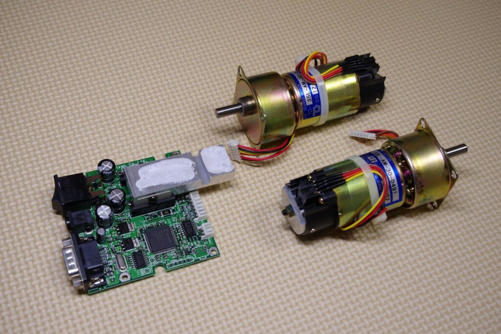
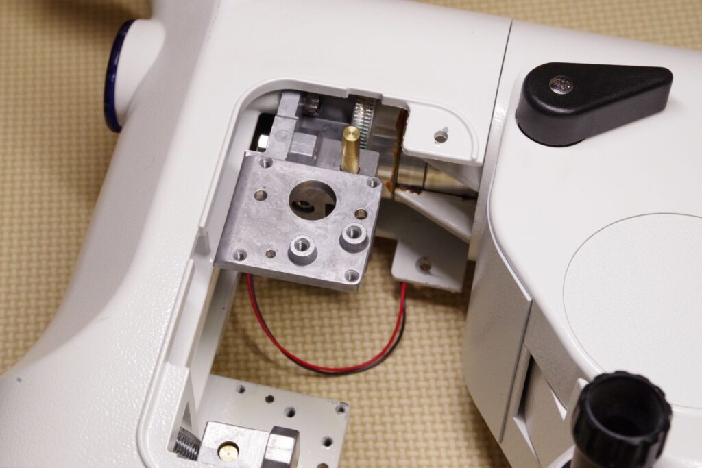
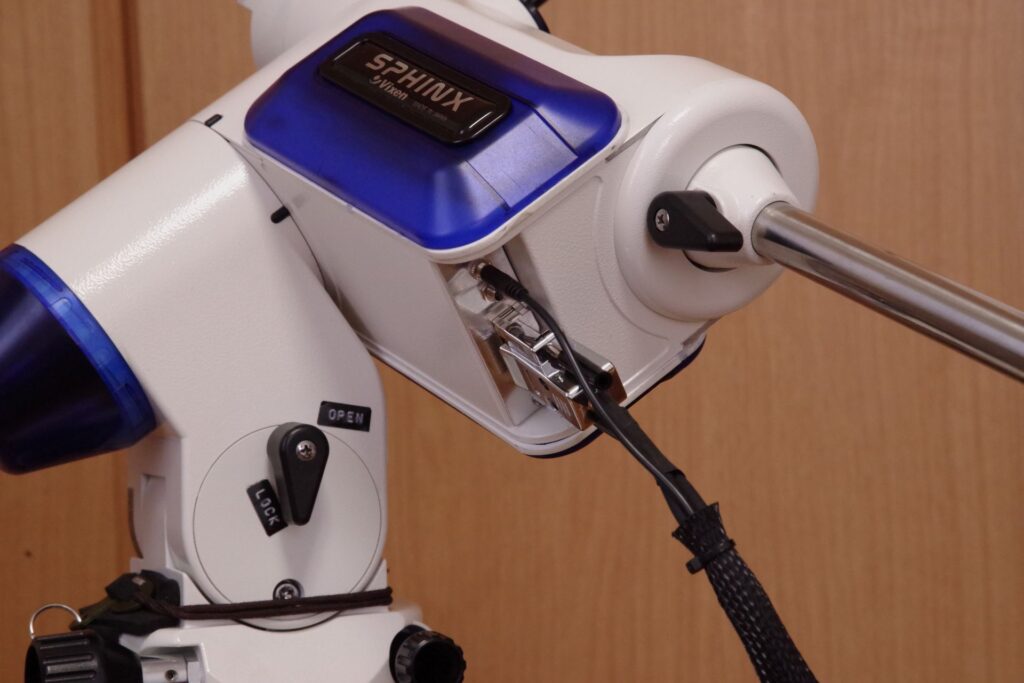
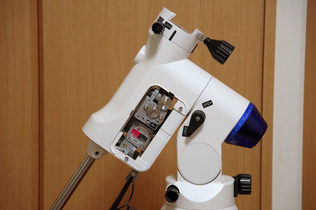
The original model uses a geared DC motor, as shown in the photo, and its control board is built into the equatorial mount itself.
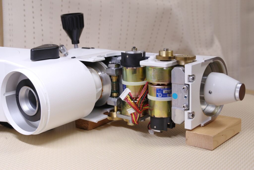
Inside the standard SX equatorial mount
Standard DC motor and controller
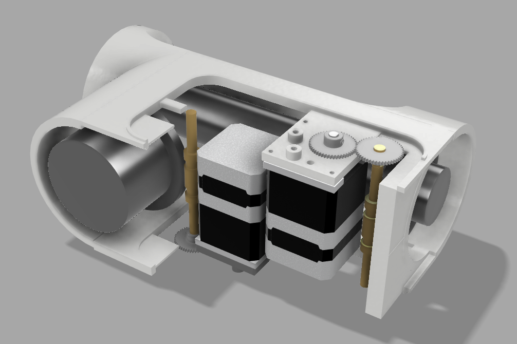
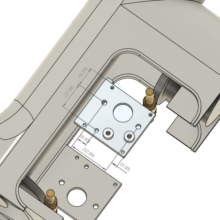
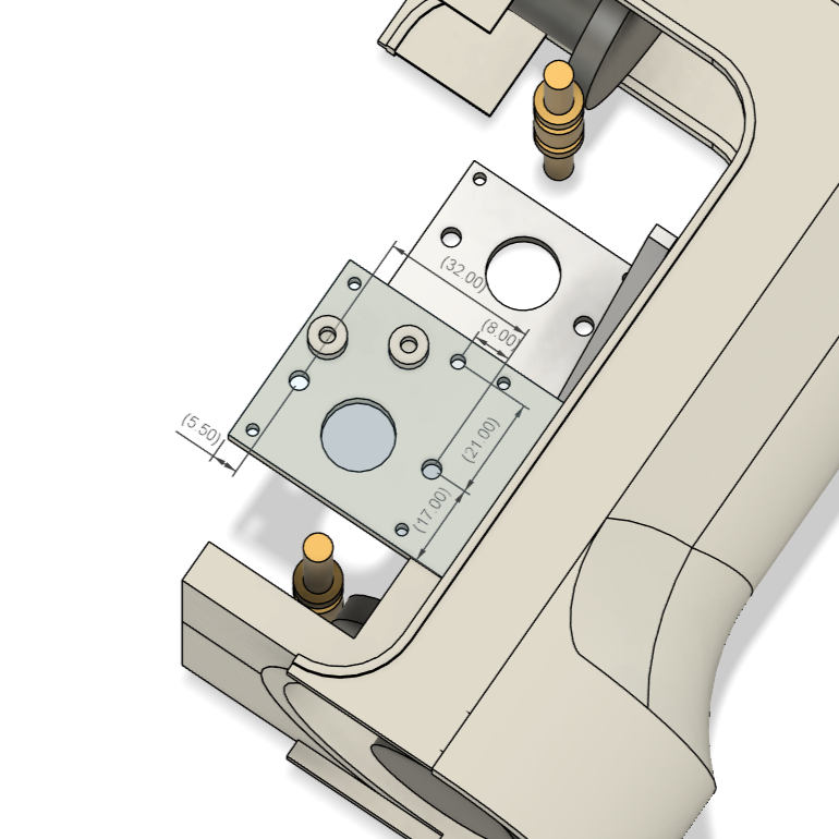
Rendered 3D image
The image on the left shows the assembly after the replacement. The motor will be replaced with a 42mm stepper motor with gears. Like the standard motor, this motor has an offset shaft, so it can be mounted in the same position with relatively little modification.
Since gearless motors have the shaft centered, they cannot be mounted using the method described here.
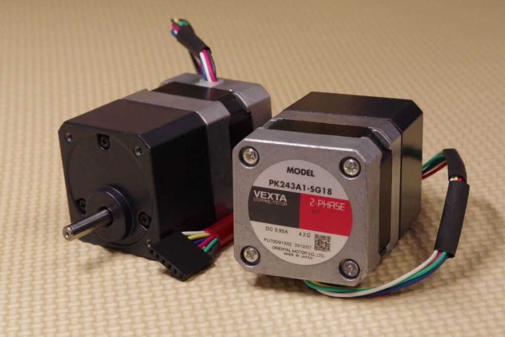
For the stepper motor, we prioritized ensuring sufficient driving force and selected a model with a relatively high reduction ratio. The maximum rotational speed of this motor is 100 rpm. However, since this geared motor has 1 degree of backlash, it presents a design disadvantage in this regard.
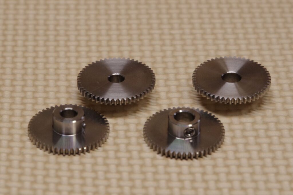
Because it is a geared motor, we designed the transmission mechanism between the motor and the worm gear shaft so that no further reduction occurs. This was done to minimize the size of the transmission mechanism and fit it inside the cover as much as possible. The gears can be ordered from Misumi.
In this system, the actual speed at which the system did not lose synchronization was 75 rpm. Converted to the speed during GOTO operation of the equatorial mount, this equates to 1.75 degrees per second (420x speed). While this is a sufficient speed for practical use, there may be room for further improvement depending on the selection of the motor and gear ratio.
In the case of the spur gears mentioned above, the center distance is 24.5 mm. A reliable method is to determine the center distance, measure the actual center distance, and select gears that match it.
The gear diameter is calculated by multiplying the number of teeth by the module. Therefore, for a module of 0.5, the center distance is calculated as (number of teeth on Gear 1 × 0.5 + number of teeth on Gear 2 × 0.5) / 2.
3. Processing
3.1 Motor Mount Plate
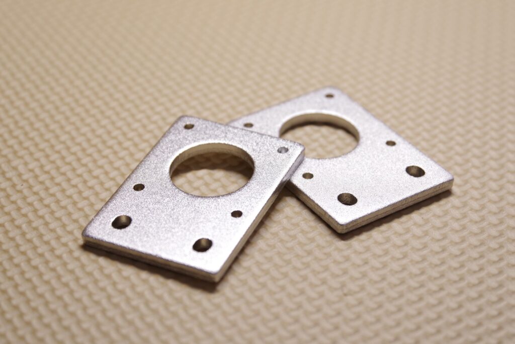
By using a commercially available motor mounting plate as a base, this can be constructed relatively easily. A 4mm-thick plate is used to ensure sufficient thickness for cutting M3 female threads. Because the relative positions of the worm gear shaft and the motor shaft differ, the designs for the declination and right ascension axes are different.
This plate is secured to the motor using M3 flat-head screws and to the equatorial mount body using M3 stud bolts.
Machined motor mounting plate
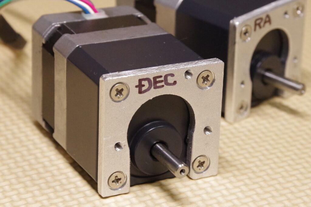
Stepper motor with a motor mounting plate attached
3.2 Modifications to the equatorial mount
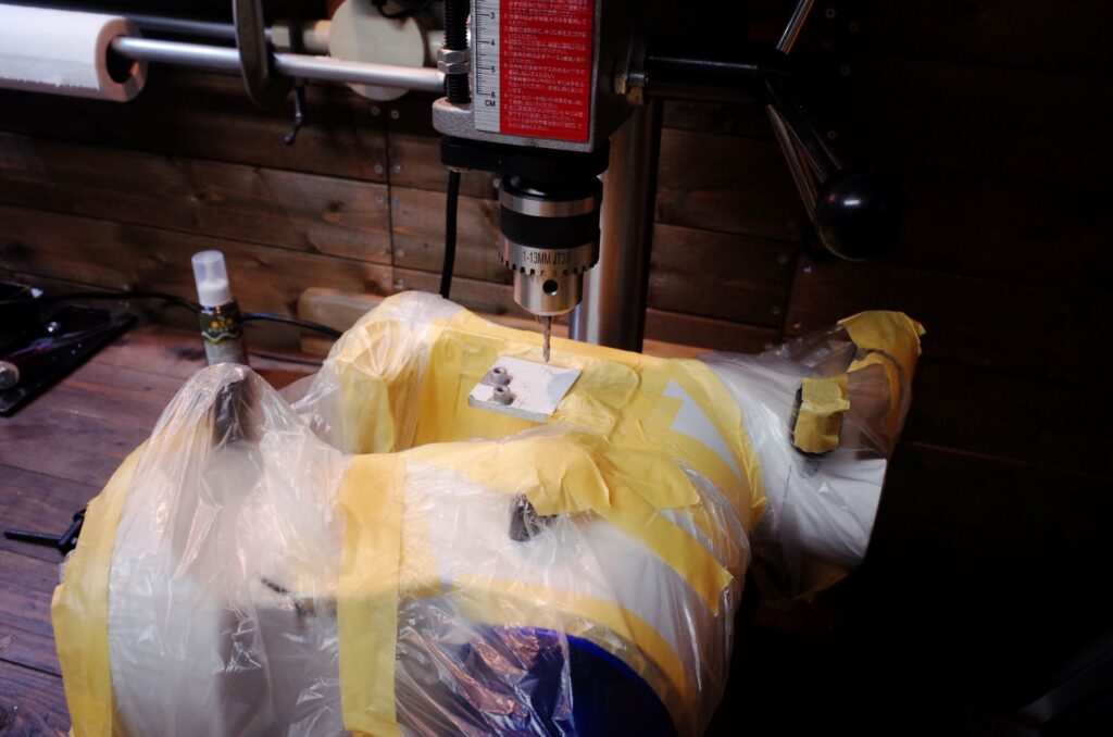
We will drill holes in the equatorial mount using a drill press. We will carefully apply masking to prevent drilling debris from entering the mount’s moving parts. The mounting holes for the stepper motor are made slightly larger to allow for belt tension adjustment. However, since the range of adjustment for the center-to-center distance is limited, precise positioning is essential. A reliable approach is to measure the actual center-to-center distance after machining and select a gear that fits that measurement.
Drill additional mounting holes using a drill press
The equatorial mount after modification
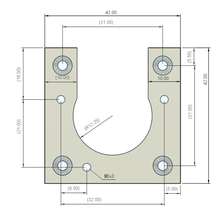
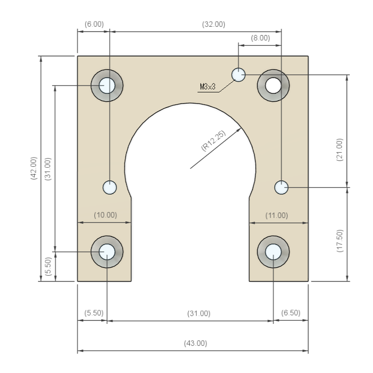
Ref: Machining drawings
Since these measurements were taken from the actual product, they may not be entirely accurate. Please use these dimensions for reference only and adjust the motor position to fit the actual product.
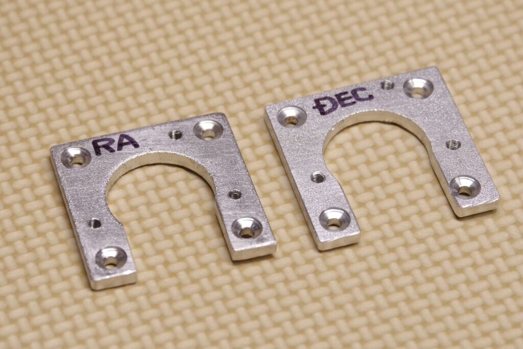
Drill hole locations on the RA-side motor mount
RA-side motor mounting plate
Position of the machined holes on the DEC-side motor mount
DEC-side motor mounting plate
4.Installing the Interface Board
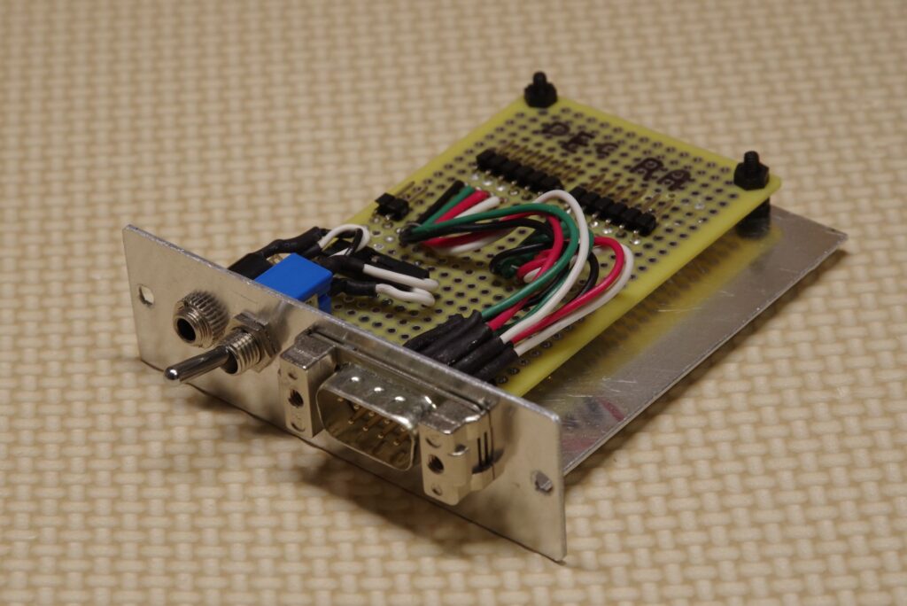
Create an interface board and install it in the location where the standard control board was originally mounted. This interface board is equipped with Mini-DIN cables for the RA and DEC motors, a jack for the dark-field illumination of the polar scope, and a toggle switch to turn the polar scope on and off. This custom-built board uses a 9-pin D-SUB connector, which makes installation easy even in dark environments and prevents the connector from coming loose since it can be secured with screws.
Equatorial Mount Interface
Interface board
5. Assembly
Install the motor and spur gear. Adjust the motor’s mounting position to ensure proper backlash. Use threadlocker on the set screws that secure the gear, as they tend to loosen easily. The genuine cover can be installed without interfering with the gear.