
SX mount to OnStep Chapter 3
OnStep Firmware Setup
1. Preparation
1.1 1.1 Installing and Configuring the Arduino IDE
Install the free development environment called Arduino IDE. This guide uses version 2.3.4.
Download of Aruduino IDE
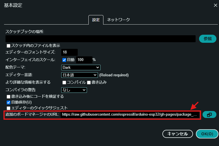
Once you have installed the Arduino IDE, start by configuring the initial settings to set up an environment for working with the ESP32.
- Enter the following two URLs in the “Additional Board Manager URLs” field.
- Open File → Preferences.
https://raw.githubusercontent.com/espressif/arduino-esp32/gh-pages/package_esp32_index.json
http://arduino.esp8266.com/stable/package_esp8266com_index.json
This allows you to download an environment that enables you to compile and program the microcontrollers you are using. The former is for the Onstep main unit (ESP32), while the latter is for the Smart Web Server (ESP8266, such as the Wemos D1 mini Pro).
1.2 Board Settings
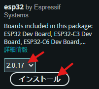
- Open Tools → Board Manager.
- Search for “ESP” to see a list of options.
- Select “esp32 by Espressif Systems.”
Be sure to select “2.0.17”—not the latest version. Other versions may cause compilation errors.
For the latest information on which version to choose, please check the OnStep official website.
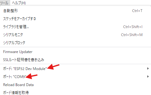
- Go to Tools → ESP32 Port and select Dev Module.
- Go to Tools → Port and select the COM port for the board connected via USB.
Check Windows Device Manager to see which COM port the connected ESP is assigned to.
Check Windows Device Manager to see which COM port the connected ESP is assigned to.
1.3 Downloading OnstepX Source Files
There are two versions of the program: Onstep and OnstepX, and several versions of each. There are also several types of circuit boards. You enter the settings in the Config.h file. I will explain the necessary Config.h settings in order. For this guide, we will be using OnstepX ver10.24c.
Although there are two versions—Onstep and OnstepX—we will be using the newer OnstepX here.
Download of OnstepX
Modify the Config.h file and other files in the downloaded source code to suit your needs, compile the code, and upload it to the microcontroller. The following sections describe how to modify the configuration files.
2. Source code modifications
2.1 Selecting the Board and Configuring Communication Settings
① Set the PINMAP to MaxESP3.
Entering the board type here will automatically load the pin configuration. For this example, we will use a board based on the MaxESP3.
② Set SERIAL_RADIO to OFF. If you are using the ESP32’s built-in Wi-Fi, set it to WIFI_ACCESS_POINT; however, since we are using an external Wi-Fi module here, set it to OFF.
Config.h
// PINMAP ------------------------------------------------- see https://onstep.groups.io/g/main/wiki/Configuration_Controller#PINMAP
#define PINMAP                   MaxESP3 //    OFF, Choose from: MiniPCB, MiniPCB2, MaxPCB4, MaxESP4, MaxSTM3, FYSETC_E4,   <-Req'd
                                          //         BTT_SKR_PRO, etc.  Other boards and more info. in ~/src/Constants.h

// SERIAL PORT COMMAND CHANNELS --------------------- see https://onstep.groups.io/g/main/wiki/Configuration_Controller#SERIAL_PORTS
#define SERIAL_A_BAUD_DEFAULT        9600 //   9600, n. Where n=9600,19200,57600,115200,230400,460800 (co
2.2 Selecting LED Functions
The LED can be used as a status indicator or for the Rectile.
Use this channel to control the LED for the polar scope built into the SX equatorial mount. To do so, make the following changes: Set RECTILE_LED_DEFAULT to a value between 0 and 255 to adjust the LED brightness. A value of 0 is the brightest, and 255 is the dimmest. When using the LED on the SX equatorial mount’s built-in polar scope, a value around 252 provides an appropriate brightness level.
If a hand controller is connected, you can adjust the brightness using the hand controller.
Config.h
// STATUS --------------------------------------------- see https://onstep.groups.io/g/main/wiki/Configuration_Controller#STATUS_LED
#define STATUS_LED                    OFF //    OFF, Steady illumination if no error, blinks w/error code otherwise.          Option

// RETICLE CONTROL ------------------------------- see https://onstep.groups.io/g/main/wiki/Configuration_Controller#RETICLE_CONTROL
#define RETICLE_LED_DEFAULT           252 //    OFF, n. Where n=0..255 (0..100%) activates feature sets default brightness.   Option
#define RETICLE_LED_MEMORY            OFF //    OFF, ON Remember reticle brightness across power cycles.                      Option
#define RETICLE_LED_INVERT            OFF //    OFF, ON Inverts control for cases where 0V is max brightness.                 Option
2.3 Selecting a Motor Driver and Setting the Drive Speed
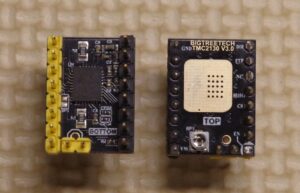
Onstep supports several types of motor drivers. Modify the AXISx_DRIVER_MODEL in Config.h to match the motor driver you are using.
In this example, we will use the TMC2130.
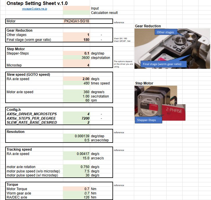
Rewrite the code to match the motor specifications and gear ratios of the equatorial mount.
Enter the specifications into this Excel sheet, and it will calculate the values to be entered into the Config.h code.
Also, configure the parameters for each motor (for each axis).
- Gear Reduction / Other steps
Gear ratio between the motor and the worm gear: The gear ratio for the equatorial mount described here is 1. For reference - Gear Reduction / Final stages
Worm gear ratio: The gear ratio for the SX equatorial mount is 180. - Step Motor / Stepper-steps
Stepper motor step size:
Since a geared motor is used here, the step size is 0.1 degrees. - Step Motor / Micro-steps :Microstepping By dividing the stepper motor’s step size, you can increase angular resolution. The available values vary depending on the motor driver. There are also limitations based on the microcontroller’s processing speed. In this case, we have selected 4. (If the motor does not operate normally when the number is set too high, reduce the value.)
- Slew speed is the speed during mGOTO operations. Here, it is set to 2.0, which is 480x speed. This is set slower than the SX equatorial mount’s 5 deg/s (1200x speed). It is best to adjust this according to the situation.
We will modify the code in Config.h based on the values of the variables defined in Config.h.
About other parameters
- AXIS1_REVERSE
This setting determines the rotation direction of the stepper motor. If, when you actually run the motor, the equatorial mount’s axis rotates in the opposite direction, toggle this setting between ON and OFF. - AXIS1_DRIVER_MICROSTEPS_GOTO
Since step resolution is not required for GOTO operations, set this to 1.
With the TMC2130, you can set the motor current via the software. Set it roughly within the limits of the motor and driver.
(The PK243 motor is rated at 0.95A, and the BIGTREETECH TMC2130 driver has a rated current of 1.2A.)
- AXIS1_DRIVER_IHOLD
- AXIS1_DRIVER_IRUN
- AXIS1_DRIVER_IGOTO
Config.h
// AXIS1 RA/AZM -------------------------------------------------------- see https://onstep.groups.io/g/main/wiki/Configuration_Axes
#define AXIS1_DRIVER_MODEL            TMC2130 //    OFF, Enter motor driver model (above) in both axes to activate the mount.    <-Often

// If runtime axis settings are enabled changes in the section below will be ignored (disable in SWS or by wiping NV/EEPROM):
// \/ \/ \/ \/ \/ \/ \/ \/ \/ \/ \/ \/ \/ \/ \/ \/ \/ \/ \/ \/ \/ \/ \/ \/ \/ \/ \/ \/ \/ \/ \/ \/ \/ \/ \/ \/ \/ \/ \/ \/ \/
#define AXIS1_STEPS_PER_DEGREE      7200 //  12800, n. Number of steps per degree:                                          <-Req'd
                                          //         n = (stepper_steps * micro_steps * overall_gear_reduction)/360.0
#define AXIS1_REVERSE                ON //    OFF, ON Reverses movement direction, or reverse wiring instead to correct.   <-Often
#define AXIS1_LIMIT_MIN              -180 //   -180, n. Where n= -90..-360 (degrees.) Minimum "Hour Angle" or Azimuth.        Adjust
#define AXIS1_LIMIT_MAX               180 //    180, n. Where n=  90..
// AXIS2 DEC/ALT ------------------------------------------------------- see https://onstep.groups.io/g/main/wiki/Configuration_Axes
#define AXIS2_DRIVER_MODEL TMC2130 // OFF, Enter motor driver model (above) in both axes to activate the mount. <-Often
// If runtime axis settings are enabled changes in the section below will be ignored (disable in SWS or by wiping NV/EEPROM):
// \/ \/ \/ \/ \/ \/ \/ \/ \/ \/ \/ \/ \/ \/ \/ \/ \/ \/ \/ \/ \/ \/ \/ \/ \/ \/ \/ \/ \/ \/ \/ \/ \/ \/ \/ \/ \/ \/ \/ \/ \/
#define AXIS2_STEPS_PER_DEGREE 7200 // 12800, n. Number of steps per degree: <-Req'd
// n = (stepper_steps * micro_steps * overall_gear_reduction)/360.0
#define AXIS2_REVERSE OFF // OFF, ON Reverses movement direction, or reverse wiring instead to correct. <-Often
#define AXIS2_LIMIT_MIN -90 // -90, n. Where n=-90..0 (degrees.) Minimum allowed Declination or Altitude. Infreq
#define AXIS2_LIMIT_MAX 90 // 90, n. Where n=0..90 (degrees.) Maximum allowed Declination or Altitude. Infreq
#define AXIS2_DRIVER_MICROSTEPS 4 // OFF, n. Microstep mode when tracking. <-Req'd
#define AXIS2_DRIVER_MICROSTEPS_GOTO 1 // OFF, n. Microstep mode used during slews. OFF uses _DRIVER_MICROSTEPS. Option
// for TMC2130, TMC5160, TMC2209, TMC2226 STEP/DIR driver models:
#define AXIS2_DRIVER_IHOLD 300 // OFF, n, (mA.) Current during standstill. OFF uses IRUN/2.0 Option
#define AXIS2_DRIVER_IRUN 600 // OFF, n, (mA.) Current during tracking, appropriate for stepper/driver/etc. Option
#define AXIS2_DRIVER_IGOTO 800 // OFF, n, (mA.) Current during slews. OFF uses IRUN. Option
// /\ /\ /\ /\ /\ /\ /\ /\ /\ /\ /\ /\ /\ /\ /\ /\ /\ /\ /\ /\ /\ /\ /\ /\ /\ /\ /\ /\ /\ /\ /\ /\ /\ /\ /\ /\ /\ /\ /\ /\ /
// SLEWING BEHAVIOUR ------------------------------------------ see https://onstep.groups.io/g/main/wiki/Configuration_Mount#SLEWING
#define SLEW_RATE_BASE_DESIRED        1.75 //    1.0, n. Desired slew rate in deg/sec. Adjustable at run-time from            <-Req'd
                                          //         1/2 to 2x this rate, and as performace considerations require.
#define SLEW_RATE_MEMORY              OFF //    OFF, ON Remembers rates set across power cycles.                              Option
#define SLEW_ACCELERATION_DIST        5.0 //    5.0, n, (degrees.) Approx. distance for acceleration (and deceleration.)      Adjust
#define SLEW_RAPID_STOP_DIST          2.0 //    2.0, n, (degrees.) Approx. distance required to stop when a slew              Adjust
                                          //         is aborted or a limit is exceeded.
#define GOTO_FEATURE                   ON //     ON, Use OFF to disable mount Goto features.                                  Infreq
#define GOTO_OFFSET                  0.25 //   0.25, Offset in deg's for goto target unidirectional approach, 0.0 disables    Adjust
#define GOTO_OFFSET_ALIGN             OFF //    OFF, ON skips final phase of goto for align stars so user tends to approach   Option
                                          //         from the correct direction when centering.
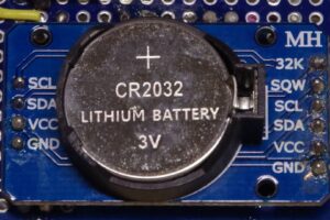
2.4 RTC (Real-Time Clock) (Optional)
Using an RTC (Real-Time Clock) is a convenient way for Onstep to keep track of the time.
By using an RTC, Onstep can retain the time even when the power is off, saving your time of setting the time every time.
Config.h
// TIME AND LOCATION ---------------------------------------------- see https://onstep.groups.io/g/main/wiki/Configuration_Mount#TLS
#define TIME_LOCATION_SOURCE DS3231 // OFF, DS3231 (I2C,) SD3031 (I2C,) TEENSY (T3.2 etc,) GPS, or NTP source. Option
// Provides Date/Time, and if available, PPS & Lat/Long also.
#define TIME_LOCATION_PPS_SENSE OFF // OFF, HIGH senses PPS (pulse per second,) signal rising edge, or use LOW for Option
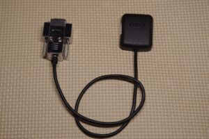
// falling edge, or use BOTH for rising and falling edges.3.3.4 GPS Receiver (Optional)
You can also use a GPS receiver. This allows the system to automatically detect both the time and location. However, you cannot use both the RTC and GPS simultaneously.
You can use any GPS device capable of serial communication in NEMA format. Here, we are using the GT-502MGG-N, which is available from Akizuki Denshi.
Config.h
// TIME AND LOCATION ---------------------------------------------- see https://onstep.groups.io/g/main/wiki/Configuration_Mount#TLS
#define TIME_LOCATION_SOURCE GPS // OFF, DS3231 (I2C,) SD3031 (I2C,) TEENSY (T3.2 etc,) GPS, or NTP source. Option
// Provides Date/Time, and if available, PPS & Lat/Long also.
#define SERIAL_GPS Serial
#define TIME_LOCATION_PPS_SENSE OFF // OFF, HIGH senses PPS (pulse per second,) signal rising edge, or use LOW for Option
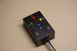
// falling edge, or use BOTH for rising and falling edges.2.5 Hand Controller Settings (Optional)
The equatorial mount can be controlled via SWS using your smartphone’s touchscreen. However, when operating in the dark, mechanical switches—such as those found on a hand controller—are much easier to use than a smartphone touchscreen.
To use the hand controller, turn on each flag.
Config.h
// ST4 INTERFACE -------------------------------------------------- see https://onstep.groups.io/g/main/wiki/Configuration_Mount#ST4
// *** It is up to you to verify the interface meets the electrical specifications of any connected device, use at your own risk ***
#define ST4_INTERFACE                 ON //    OFF, ON enables interface. <= 1X guides unless hand control mode.             Option
                                          //         During goto btn press: aborts slew or continue meridian flip pause home
#define ST4_HAND_CONTROL               ON //     ON, ON for hand controller special features and SHC support.                 Option
                                          //         Hold [E]+[W] btns >2s: Guide rate   [E]-  [W]+  [N] trk on/off [S] sync
                                          //         Hold [N]+[S] btns >2s: Usr cat item [E]-  [W]+  [N] goto [S] snd on/off
#define ST4_HAND_CONTROL_FOCUSER       ON //     ON, ON alternate to above: Focuser move [E]f1 [W]f2 [N]-     [S]+            Option
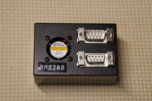
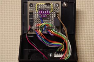
2.6 Configuring the Temperature, Humidity, and Barometric Pressure Sensors (Optional)
By installing the BME280, you can measure temperature, humidity, and atmospheric pressure.
The BME280 uses I2C communication. With the SDOpin, you can select one of two I2C addresses for the BME280.
| SDO | 2Cアドレス | WEATHER |
| VDD | 0x77 | BME280 |
| GND | :0x76 | BME280_0x76 |
Config.h
// WEATHER SENSOR --------------------------------- see https://onstep.groups.io/g/main/wiki/Configuration_Controller#WEATHER_SENSOR
#define WEATHER                       BME280 //    OFF, BME280 (I2C 0x77,) BME280_0x76, BME280_SPI (see pinmap for CS.)          Option
                                          //         BMP280 (I2C 0x77,) BMP280_0x76, BMP280_SPI (see pinmap for CS.)
                                          //         BME280 or BMP280 for temperature, pressure.  BME280 for humidity also.
4. Smart Web Server
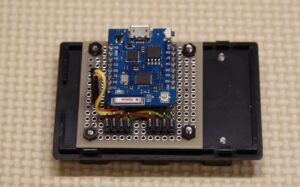
The Wemos D1 Pro is used as the hardware for the Smart Web Server. The program is written directly to the Wemos D1 Pro using the Arduino IDE.
By using the SWS, you can communicate with Onstep via Wi-Fi using a PC or smartphone. Additionally, the SWS connects to the main unit via serial communication.
4.1 ボードの設定
You can download Smart Web Server here.
ダウンロードサイト
(Just like in Step 2, install the Board Manager.)
- Open Tools → Board Manager.
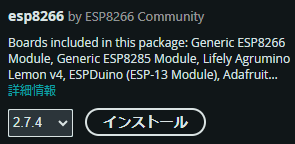
- Search for “ESP8266” to display several options.
- Select “esp8266 by ESP8266 Community.”
Be sure to select “2.7.4” rather than the latest version. Other versions may cause compilation errors. Please check the OnStep official website for the latest information on the recommended version.1.
- Under Tools → Port ESP8266, select LOLIN(WEMOS)D1 mini Pro
- Under Tools → Port, select the COM port for the board connected via USB
Check Windows Device Manager to see which COM port the connected ESP is assigned to.
4.2 Modifying the Smart Web Server Source Files
The Smart Web Server allows you to choose between “Access-Point mode (AP)” and “Station mode (STA)”; by default, it is set to “Access-Point mode”.
Access-Point mode:
This mode is enabled by default, and OnStep operates as an access point. Here, you can change the access point name and password as desired. The Smart Web Server hardware uses a Wemos D1 Pro. The program is written directly to this Wemos D1 Pro using the Arduino IDE.
By using SWS, you can communicate with OnStep via Wi-Fi using a PC or smartphone. Additionally, SWS communicates via UART.
Station mode (connect to Access Point):
This configuration connects OnStep or a PC to an access point, such as a home server. Enter the access point’s SSID and password, and set OnStep’s IP address. OnStep automatically connects to the access point upon startup. Entering OnStep’s IP address in a PC browser will display the SWS screen.
Extended.config.h
// These settings are stored in NV (EEPROM) and the SWS will not recognize the settings below except on the first upload unless
// NV is wiped, these settings (where applicable) can be changed at runtime however.
#define AP_ENABLED                  true //        true, Wifi Access Point Enabled.                                          Adjust
#define AP_SSID                  "ONSTEP" //    "ONSTEP", Wifi Access Point SSID.                                             Adjust
#define AP_PASSWORD            "password" //  "password", Wifi Access Point password.                                         Adjust
#define AP_CHANNEL                      7 //           7, Wifi Access Point channel.                                          Adjust
#define AP_IP_ADDR          {192,168,0,1} // ..,168,0,1}, Wifi Access Point IP Address.                                       Adjust
#define AP_GW_ADDR          {192,168,0,1} // ..,168,0,1}, Wifi Access Point GATEWAY Address.                                  Adjust
#define AP_SN_MASK        {255,255,255,0} // ..55,255,0}, Wifi Access Point SUBNET Mask.                                      Adjust

#define STA_ENABLED                 false //       false, Wifi Station Enabled.                                               Adjust
#define STA_SSID                 "Home" //      "Home", Wifi Station SSID to connnect to.                                   Adjust
#define STA_PASSWORD           "password" //  "password", Wifi Station mode password.                                         Adjust
#define STA_DHCP_ENABLED            false //       false, Wifi Station/Ethernet DHCP Enabled.                                 Adjust
#define STA_IP_ADDR        {192,168,1,55} // ..168,1,55}, Wifi Station/Ethernet IP Address.                                   Adjust
#define STA_GW_ADDR         {192,168,1,1} // ..,168,1,1}, Wifi Station/Ethernet GATEWAY Address.                              Adjust
#define STA_SN_MASK       {255,255,255,0} // ..55,255,0}, Wifi Station/Ethernet SUBNET Mask.                                  Adjust