SX to OnStep Chapter 2
OnStep System
This page describes the system configuration of the Onstep controller featured here.
1. OnStep Hardware Configuration
We use the open-source OnStep system to control the equatorial mount. Click here to visit the official OnStep website.
Some of the OnStep hardware specifications have been made public. Here, we present a modified version of the system based on the ESP32 ver3.
*We are using a board that was made available for distribution.
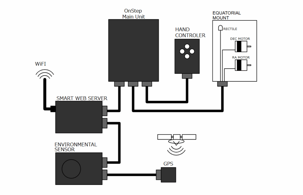
2. System Configuration
2.1 Onstep Main Unit
ONStep ESP32 ver3 is a version that uses the ESP32-DevKitC-32E microcontroller development board.
With OnStep, you can configure and retrieve time and location information in the following three ways:
- Manually configure using Smart Web Server (SWS) from a PC or smartphone
- Use the RTC (Real-Time Clock) to maintain the time internally within OnStep
- Connect a GPS receiver to automatically acquire location and time from satellites
The system is designed to retain the time even when the power is turned off using the DS3231 Real-Time Clock (RTC). Additionally, some RTC and GPS modules support the 1PPS (1 Pulse Per Second) signal, enabling high-precision synchronization of the internal time within OnStep.
The ESP32-DevKitC-32E is available for purchase at Akizuki Denshi Tsushou. → Click here for the product page
2.2 Basic Hand Controller
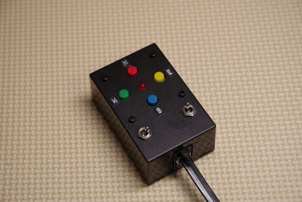
By using the Smart Web Server described below, you can control the equatorial mount via a smartphone or PC. However, operating the mount via a touchscreen can be inconvenient when trying to check the star image in the dark.
This is where this hand controller comes in handy. Equipped with mechanical switches, it allows for intuitive operation even in dark environments, making it extremely convenient for fine-tuning while observing the stars. This hand controller controls Onstep via the ST-4 interface.
*Please note that ST-4 interface specifications may vary slightly by device. You must verify compatibility for each specific device.
2.3 Smart Web Server (SWS)
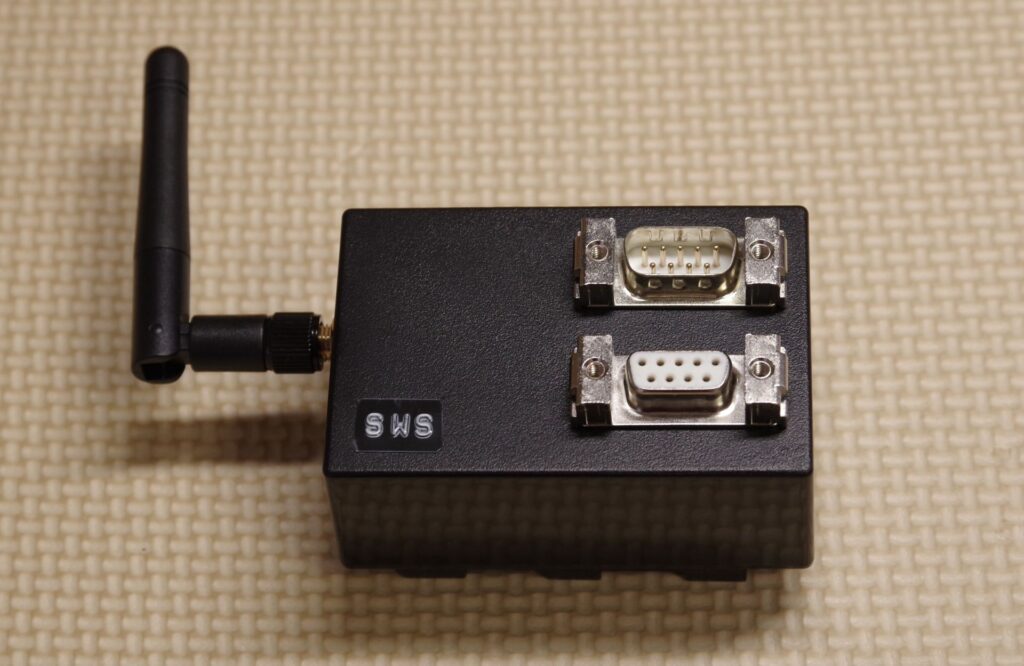
Smart Web Server (SWS) is an interface that connects to PCs and smartphones via Wi-Fi, allowing users to control OnStep through a web browser or via ASCOM.
The ESP32 microcontroller used in OnStep has built-in Wi-Fi functionality and can communicate on its own, but connections could become unstable depending on the environment. Therefore, in this configuration, we use the WEMOS D1 mini Pro exclusively as a Smart Web Server to ensure stable Wi-Fi communication.
The WEMOS D1 mini Pro also supports connection to an external Wi-Fi antenna, providing a stable connection.
2.4 Environmental sensor
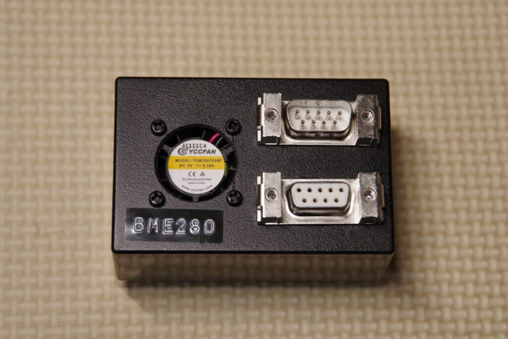
This unit is equipped with the BME280 environmental sensor, which measures temperature, humidity, and atmospheric pressure. This data will be available within the Onstep system.
While this unit is not required, the author plans to utilize it for future expansions.
2.5 GPS Unit
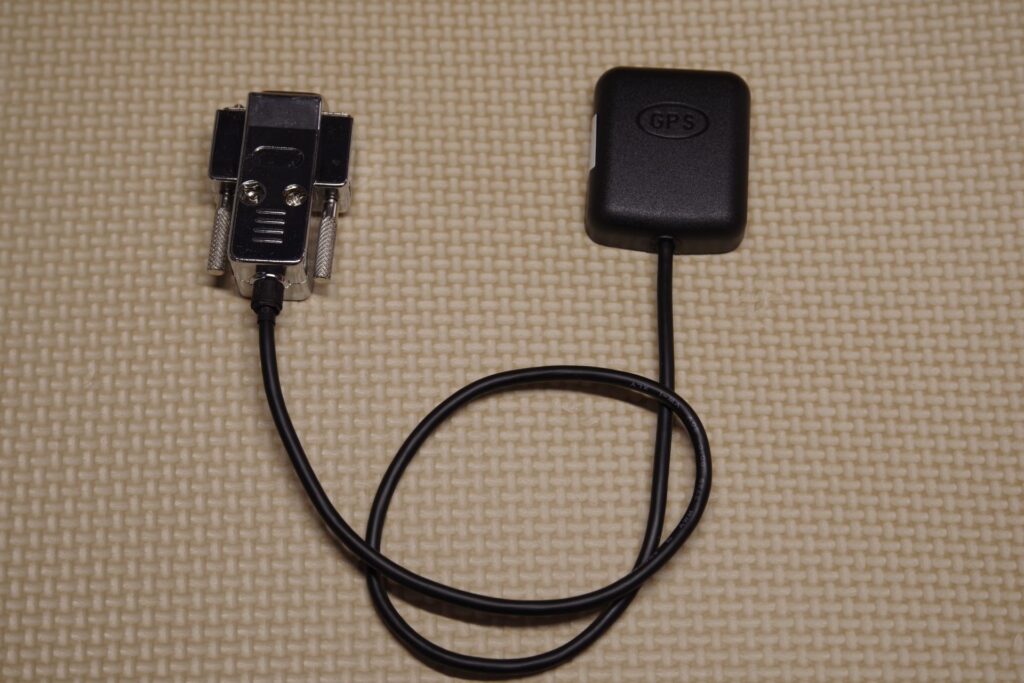
OnStep supports GPS modules that use UART communication and are compatible with the NMEA format. In this example, we are using the GT-502MGG-N as the GPS receiver.
Although USART0 is used for communication, USART0 conflicts with the USB connection to the PC, so simultaneous connection to the PC is not possible. When connecting this device, you must avoid connecting it to the PC.
The GT-502MGG-N is available for purchase from Akizuki Denshi Tsushou. → GT-502MGG-N Product Page
3. Circuit Diagram
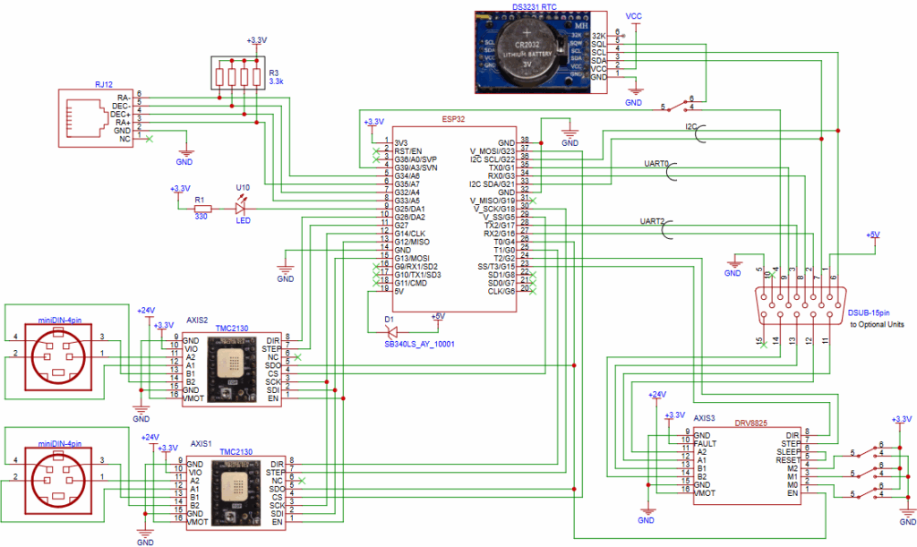
3.1 Circuit diagram of the OnStep Main Unit
This system uses the TMC2130 as the motor driver for the equatorial mount and the DS3231 as the real-time clock (RTC).
We are using a board that can accommodate up to three motor drivers, allowing us to add a driver for the motorized focuser as well.
We use OnStep for control, and the system is designed to be compatible with a variety of motor drivers. Among these, the TMC2130 is an excellent driver that allows for detailed configuration via I2C communication and combines quiet operation with high precision.
| Serial Communication (USRT2) | Connecting to Smart Web Server |
| Serial Communication (USRT0) | Connecting to the GPS module |
| I2C Communication | Connection between the OneStep unit’s built-in RTC and the optional environmental sensor (BME280) |
3.2 Circuit Diagrams for Optional Units
The optional units are designed to connect via D-SUB connectors, allowing for a flexible hardware configuration that enables users to freely switch between optional units.
*Note: You will need to modify the source code depending on the optional unit used.
Select one of the following methods for obtaining the time:
- The built-in real-time clock (RTC)
- The optional GPS module
*Note: You cannot use both at the same time.
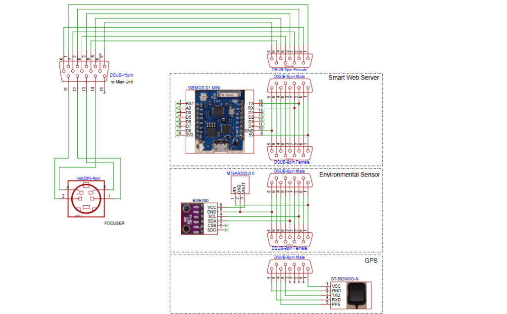
Circuit Diagrams for Optional Units
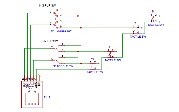
3.3 Circuit Diagram for the Basic Hand Controller
The basic hand controller operates based on the state of each terminal (open or closed). The circuit is designed to allow signal inversion using a toggle switch.